Overview
- Read EEPROM Calibration data
- Write to Control Register to choose temperature or pressure
- Task loop
- Read data register for the measurement
- Convert the raw bits to Celsius or Pascals using bit manipulation
- Take mutex, then write the measurement to the global data variable
- Update task health flag to feed the watchdog
I2C
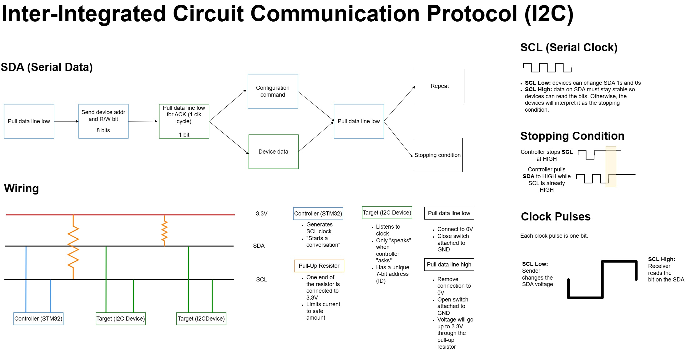
Address + W/R: 1110111 + 0/1
Write: 0xEE
Read: 0xEF
Master mode: controller initiates communication
Registers
Datasheet: https://cdn-shop.adafruit.com/datasheets/BST-BMP180-DS000-09.pdf
| Name | Bin | Hex | Description |
|---|---|---|---|
ctrl_meas | 11110100 | 0xF4 | Tells sensor when to wake up and what to measure |
| MSB | 11110110 | 0xF6 | MSB of temperature or pressure value |
| LSB | 11110111 | 0xF7 | LSB of temperature or pressure value |
| XLSB | 11111000 | 0xF8 | (Optional) XLSB of temperature or pressure value |
Control Register
| Measurement | Bin | Hex | Control Register |
|---|---|---|---|
| Temperature | 00101110 | 0x2E | ctrl_meas |
| Pressure | 11110100 | 0xF4 | ctrl_meas |
Measurements
Uncompensated temperature (UT) and uncompensated pressure (UP): raw values in bits
Hardware
- Pull-up resistors for SCL and SDA: 4.7
Calibration
EEPROM: Every time the STM32 boots up, the calibration data must be read from the EEPROM.
- Electrically erasable programmable read-only memory
- Retains data when power is lost
- Non-volatile, byt-addressed
Purpose of Calibration: imperfections in sensor
- An equation translates electrical signals read by the sensor into data
- The 11 values are the coefficients of that equation
Steps for Calibration
- Read 11 memory addresses
-
0xAA(10101010) to0xBF(10111111) - Each address has a distinct 16-bit calibration coefficient - Since I2C registers are 8 bits, split the 16-bits into MSB and LSB - Read MSB first - Combine the MSB and LSB
Oversampling Setting (OSS)
Write OSS << 6 into the control register
OSS controls the accuracy and noise level.
| Higher OSS | Lower OSS |
|---|---|
| Sensor takes more samples and averages them | Sensor takes fewer samples and averages them |
| Higher accuracy | Lower accuracy |
| Less noise | More noise |
| Longer measurement time | Shorter measurement time |
Bits 7 and 6 of the control register are for the oversampling setting.
- If OSS = 0: 0 << 6 = 0 (bits 7 and 6 are 00)
- If OSS = 1: 1 << 6 = 64 (bits 7 and 6 are 01)
- If OSS = 2: 2 << 6 = 128 (bits 7 and 6 are 10)
- If OSS = 3: 3 << 6 = 192 (bits 7 and 6 are 11)
Only pressure (not temperature) has OSS.
- Sensor hardware designed for single temperature reading, so there isn’t an option for oversampling or averaging.
- Temperature is less sensitive to noise.